About This Blog

Este es un blog dedicado al módulo de "Desarrollo y Construcción de Prototipos Electrónicos", el cual pertenece al segundo año del ciclo "Desarrollo de productos electrónicos", en el que se irá colgando cualquier tema que sea abordado en dicho ciclo.

Máquina de estados

Posted by Diego Lavín 15:58, under | No comments

Una máquina se desplaza de derechas (D) y de izquierdas (I) y dos finales de carrera (A y B). Al actuar sobre el pulsador (P) la máquina se desplaza de A hacia B efectuando una operación (X). Al llegar a B regresa hasta A sin efectuar ninguna operación.
Al llegar a A inicia un nuevo movimiento hacia B realizando una operación (Y). Cuando llega a B vuelve a A sin ejecutar ninguna operación y se queda en reposo.

Contador BCD

Posted by Diego Lavín 14:15, under | No comments


El enunciado del ejercicio es el siguiente: Implementar en el CPLD XC9572 un Contador BCD con permiso de reloj y borrado asíncrono. Su salida será decodificada a 7 segmentos sobre una DISPLAY de cátodo con de 7 segmentos.

Creamos un nuevo proyecto al igual que en los anteriores ejercicios. Colocamos un contador BCD, al que ya hemos añadido el BUFG para minimizar el skew

Tenemos que diseñar el decodificador, en este caso, en código VHDL. Seguimos los siguientes pasos:


Continuamos y se nos crea un fichero .vhd, si nos adentramos en él veremos un código como este


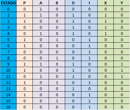
Tenemos las librerias creadas y la cabecera pero nos falta el programa en si, que lo podemos conseguir de las plantillas VHDL que el mismo programa nos proporciona. Para ello vamos a Edit-> Language Templates y buscamos un display de 7 segmentos, copiamos el código que nos haga falta en nuestro programa y ya estará


Teniendo en cuenta que dependiendo si el display es de ánodo común o de cátodo común habrá que cambiar los ceros por unos y viceversa (en la imagen es ánodo común) así que nosotros lo vamos a cambiar.
Ahora vamos a crear el símbolo y conectamos todo


Creamos el Test Bench como ya hemos hecho en otros ejercicios y nos vamos al ModelSim

 
Asignamos los pines como en la imagen


Y finalmente programar en la tarjeta, como ya hemos visto.

4-Bit binary counter

Posted by Diego Lavín 13:15, under | No comments


El siguiente ejercicio es un contador de 4 bit´s con permiso de reloj y borrado asíncrono

Seguimos los pasos del ejercicio anterior para crear un nuevo proyecto. Añadimos el CB4CE, un contador que Xilins da por defecto


Para minimizar el skew añadiremos un BUFG en el reloj


Vamos a crear un símbolo de un esquema, para ello añadimos un nuevo fichero fuente y creamos el siguiente esquema


Una vez hecho, creamos el símbolo


Ahora ya podemos seleccionarlo como si fuera un componente más y lo conectamos todo


En este ejercicio vamos a crear un fichero de restricciones para la localización de pines. Para ello vamos a Project->New Source->Implementation Constraints File.
Ahora se habrá creado un fichero .UCF en el cuál podremos poner el orden de pines deseado.


Solo queda crear el Test Bench y programarlo, exactamente igual que en el ejercicio anterior


Implementation of a 1-bit full adder in the XC9572 CPLD

Posted by Diego Lavín 13:40, under | No comments


We will use  ISE Webpack 10.1, that is a Xilinx´s application and a CPLD XC9572.
Other aplication that we have to use is ModelSim that is another application whose function is to simulate the exercise.

Our first exercise is: IMPLEMENT A 1 BIT ADDER using a CPLD (XC9572, in my case).


To understand the operation of our adder, we have to make a true table:


This table contains two input data (A and B) + the input Carry and a output data + the output Carry.

If we apply Karnaugh, our result is as follows:


The next step is to design  a schematic circuit. For this, we have to open  ISE Webpack 10.1 (Project Navigator) and we must select 'File'--> 'New Project'
Now, will be opened a window like this:

Here, we must put the Project name (sumador) and the Project location (C:\Xilinx\Projects\sumador). At last we need to select the type of source for the project that will be 'Schematic'.

In the next window, we have must to configure our device properties. The device and the family are XC9572 and XC9500 CPLDs respectively. Our Package is PC84 and the speed -7.
Later we must select the programming language that we prefer, I prefer VHDL. 
To simulate the program, I have to use ModelSim simualator.


In the new window, we select Schematic for the design and we put the Location and the File name. 
In the next window we click next because we don´t need to add any source.

Now will be opened a new window with the working environment. 
We have to go to 'Symbols' tab for select our components. In the window´s top there is a toolbar where we can select different options like 'Add wire' or 'Add Net name'.


We begin to select the components (2 AND gates, 2 XOR, 1 OR gate) and we add the nets.

Create the Test Bench file, for this, we need to create a new source and we select Test Bench Waveform.
In this window we should select the internal clock like in the image:


Now, we have to check the true table of the counter. We need to configure the time inputs for realize the simulation.


We have to add the Test Bench file to project and it will be opened ModelSim with the simulation.


Finally, we have to program the project in a CPLD.
For this we need a JTAG


An ATX power source


and the CPLD 'TAD-XC9572'.


At first we have to generate our programming file (.JED file)


When we had generated the .JED, we must go to Impact (Xilinx´s application). And program the CPLD.